Fuselage
August, 2010 – First Entry
I started by building a 16’ bench using mostly left over lumber from a tree-house I built for my son last year. The bench surface is ¾” particle board, which honestly I don’t recommend. It seems pretty strong and inexpensive, but sags under its own weight unless well supported. It took a long time to lay out the lines for the fuselage sides. I drew them directly onto the bench surface, and had to redraw several lines until I got everything right. It pretty much took a weekend and several evenings. I found a laser level to be a great tool for laying out long straight lines.
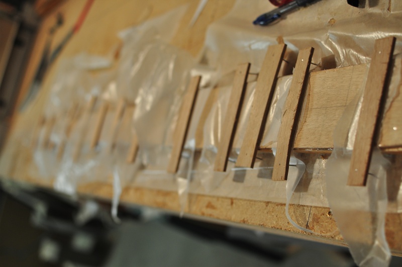
The first fuselage side took another week as I had to learn how to use my new power tools. Cutting and fitting the sticks wasn’t too hard, and was similar to model airplane building. These photos show the fuse side frames laid out on the workbench. 1/2” scrap wood blocks are used to hold the sticks in place and ensure that both sides are identical. The ½” blocks are shorter than the ¾” doug fir sticks. This allows the builder to glue one of the fuse sides to the sticks without removing it from the table.
The bottom of the fuselage sides have two ¾” sticks close to one another. A bit of ¾” plywood acts as a spacer at the front end. The front of the fuselage is hardwood to better support the firewall and engine mount.
The fuselage frames are skinned with 1/8” plywood. I couldn’t find 1/8” so I’m using 4mm. This will likely add additional weight on top of my doug fir sticks. I may need to route holes in the side to reduce weight. The fuselage is approx 15” long, but plywood only comes in 8 ft. lengths. You have to scarf two pieces together. You can make both fuse sides out of two sheets. I hand sanded the bevel for scarf. It’s not perfect, but it’s strong. At the halfway point of each fuse side is where the scarf joint occurs. The seam is clearly visible in this photo. There’s an obvious difference in the color of the two pieces of plywood.
I glued the ply wood sides to the fuse frames with T-88 Epoxy. The plans call for using aircraft quality nails to hold the sides in place and apply pressure until the flue dries. The designer recommends roughly 1” spacing for the nails, and suggests that you simply pound them directly into the plywood and leave them. On one side I did exactly that, on the other side I used nailing strips and removed the nails once the glue set. We’ll see if the nails in the one side cause problems for covering down the road.
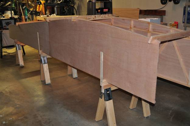
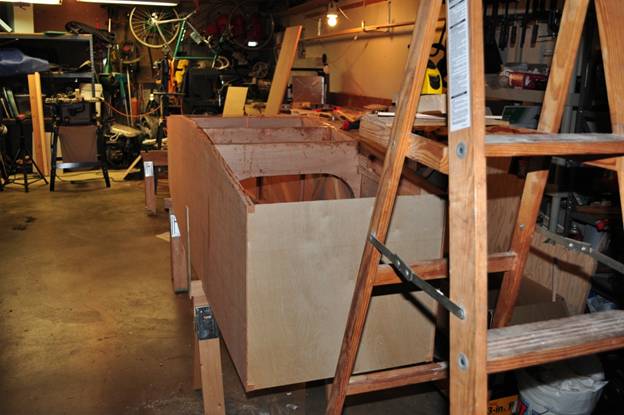
Once both sides are complete, you set them upright parallel to one another and start building the stations (or bulkheads) between them.
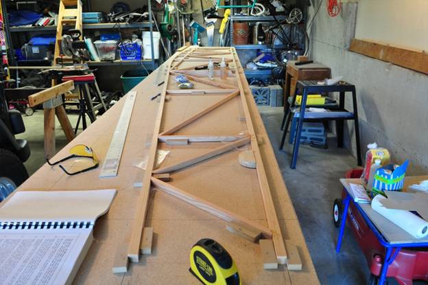
In the photo above, the boards across the top of the fuse sides are just there to act as spacers. I built some short saw horses for the fuselage to sit on. This raises it to a more comfortable level. The fuse sits on the saw-horses inverted. There are long vertical sticks coming off the sides of the sawhorses, these were just to support the sides in case they fell while I was setting everything in place.
The stations (bulkheads) are built up of many pieces. I used a combination of dougfir, spruce and plywood.
First 3/4 doug fir sticks are glued between fuse sides as seen below.
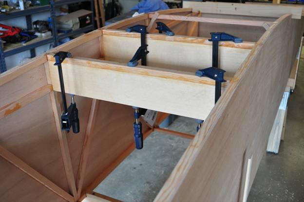
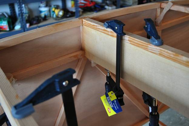
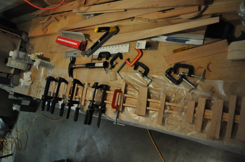
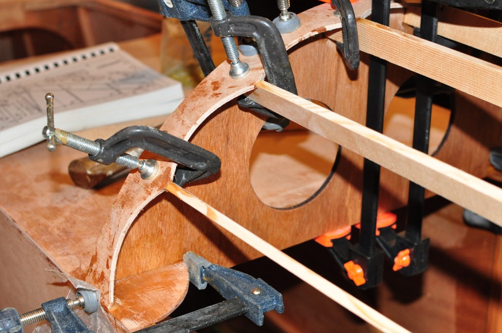
Then spruce boards are glued in place beneath them (really on top of them since the fuse is inverted). I buy my clamps from Harbor Freight. They often have them on sale. The more you have the more pieces you can glue up at once.
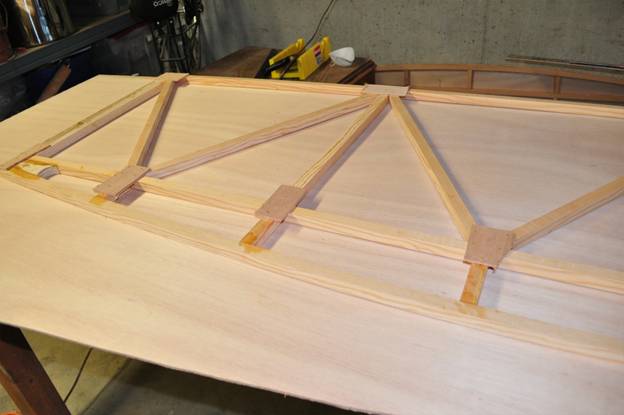
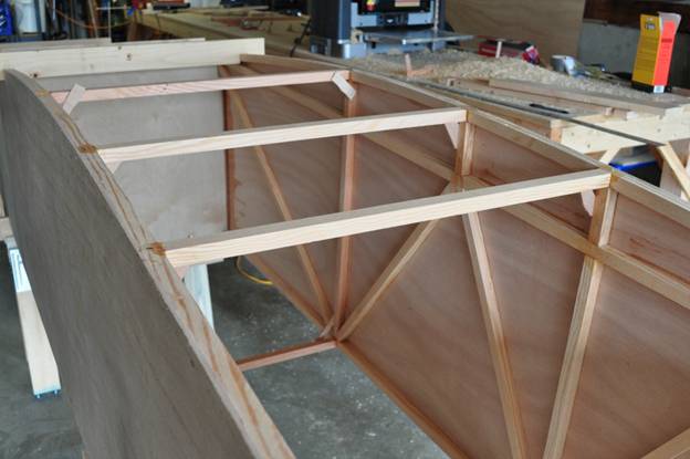
Plywood corner bows (below) reinforce the bulkhead pieces, and the whole thing is sheeting in plywood.
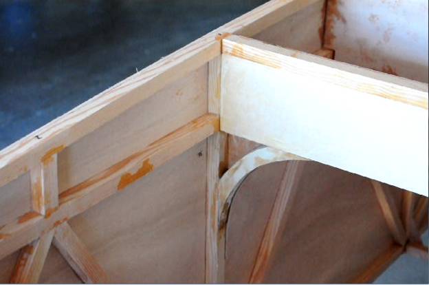
Many areas of the flybaby are hollow, and must be varnished before being sealed up. The plans state that the FAA has to be given an opportunity to inspect these, but my local DAR stated that this was not required. Just in case, I created movies of myself varnishing some areas for evidence.
The stations (bulkheads) with plywood sheeting, and ¾” plywood reinforcement blocks. The plywood at the firewall location is just cheap stuff to help with alignment. The real firewall is installed later. Station 2 is not glued in place yet, nor is it even in the correct position. I’m experimenting with building it a little differently than the others.
September 6, 2010
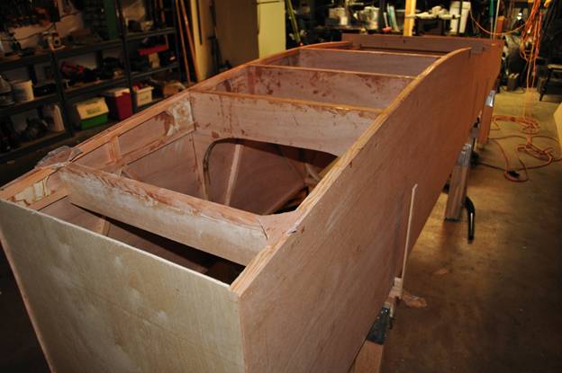
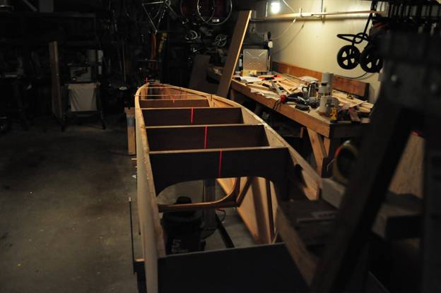
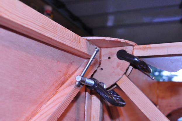
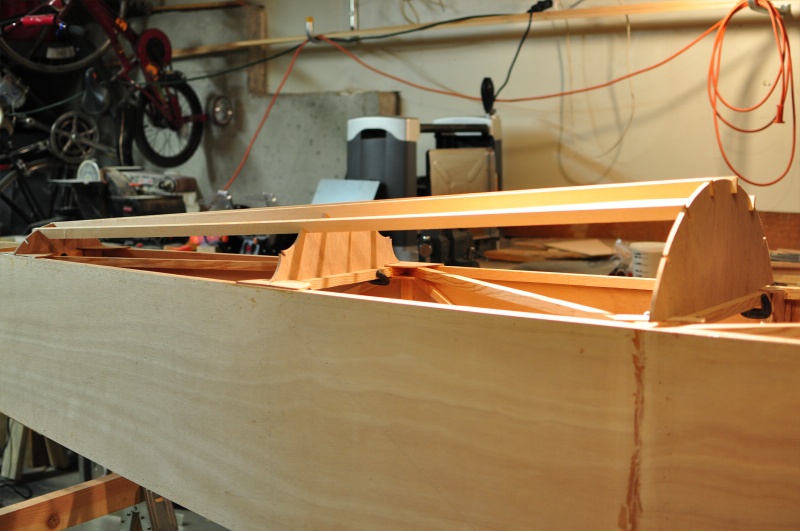
As the forward stations are nearing completion, I’ve started to pull the rear of the fuselage sides together in preparation for building in stations 6, 7, and 8. To ensure everything is properly aligned, I pulled the sides together and held them with temporary strips of wood nailed across the 2 sides. I then marked the center of each piece, and used the light from a laser level to make sure both sides are aligned properly. Here’s a photo with the light on showing the laser sitting on a ladder. If you look carefully you can see the red laser marks on the stations.
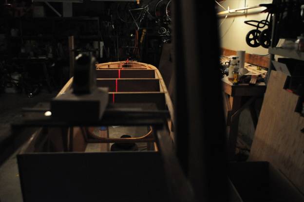
It’s easier to see the red laser marks with the lights out below.
This next photo is taken right behind the laser. The fuse sides lined up pretty nicely on their own, but a little nudging here and there made them even better.
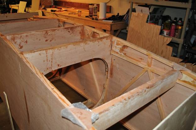
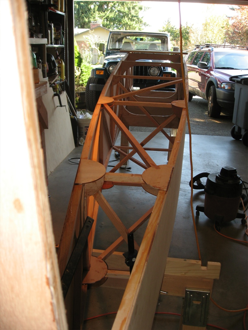
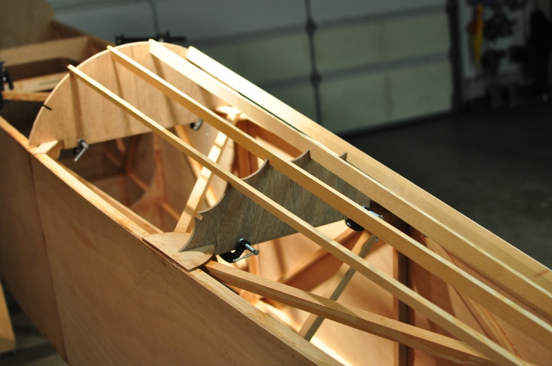
The next photo shows the first pieces glued in for stations 6,7, and 8.
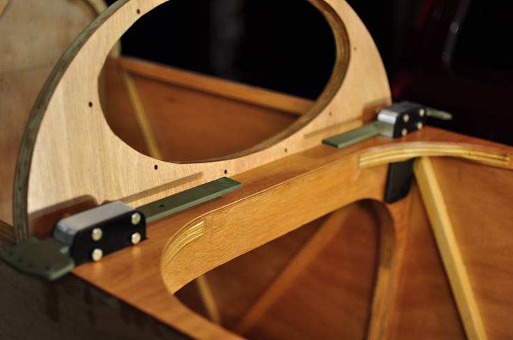
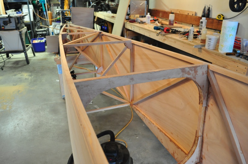
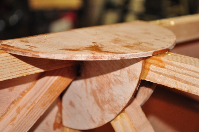
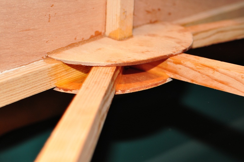
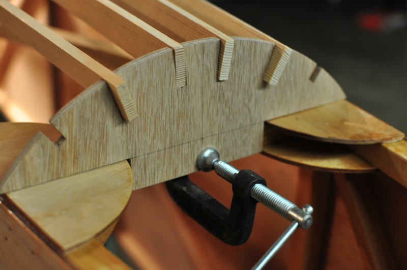
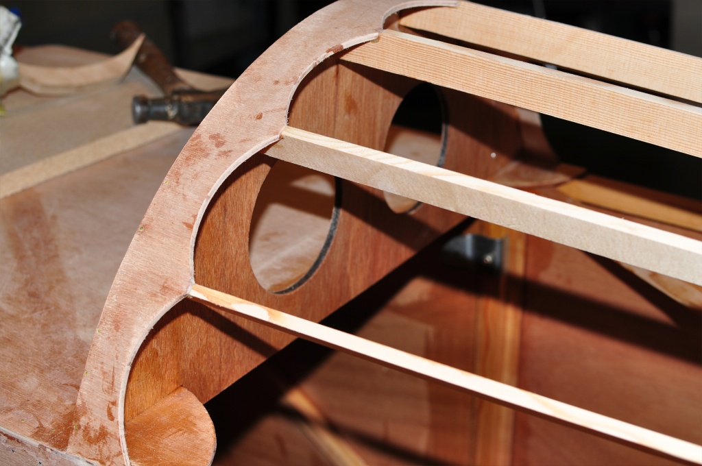
Half and quarter circle gussets are used to reinforce the rear stations. Here’s one for station 6. Holes drilled in the quarter round gusset are for drainage.
And a view of the bottom (Fuse is still upside-down) of station 7 gussets.
December 28, 1010
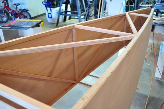
I’ve pulled the fuselage sides together at the tail and inserted all the cross-members. The cross-members are all ¾” douglas fir sticks gusseted with 4mm plywood.
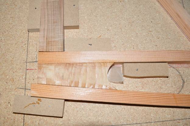
There are two types of gussets used. The one pictured below is used to reinforce a vertical horizontal cross-member.
The gusset picture below is used to reinforce horizontal diagonal cross members.
Still a few more gussets needed below.
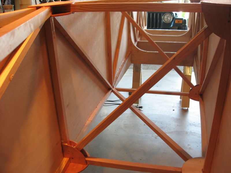
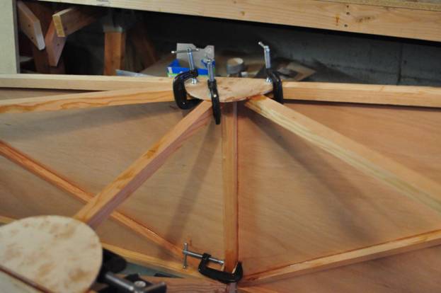
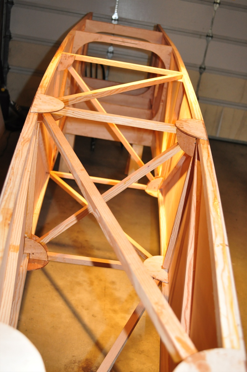
Top View of gusseted fuselage.
Rudder post is a built up hollow structure with 3/8” thick blocks and side sticks and 4mm plywood skins. Here are all the pieces being glued together except for the top skin. This is actually the third rudder post I built. The first one had a bad glue joint, the second one was built per the plans, but I didn’t notice the correction on page 9-7 (it was buried in the back of the book under a paragraph titled “Another Correction”). I actually had the second rudder post glued to the fuselage before I realized the error. Cutting it off was a real pain.
Here’s the nearly complete rudder post, varnished and ready for the top skin.
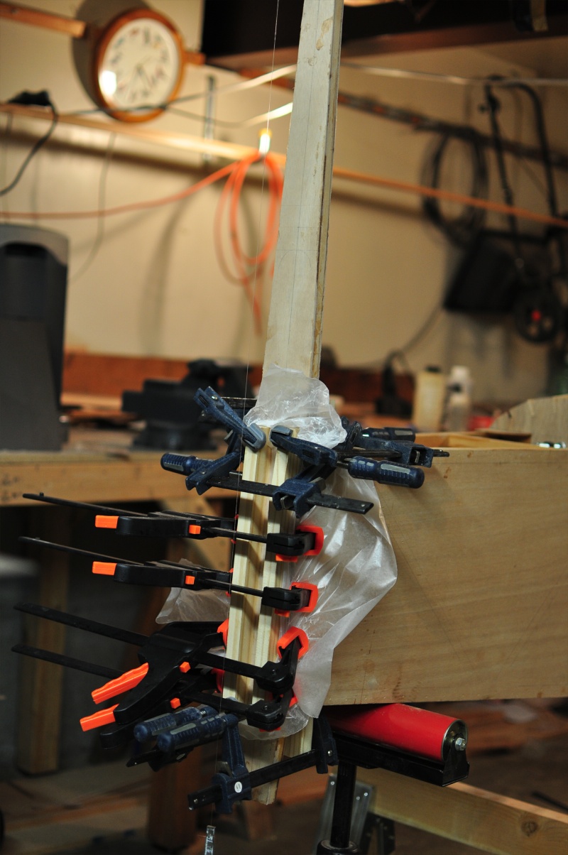
Top skin being glued on the rudder post. I used scrap plywood and nails to tightly strap the top skin to the rudder post until the epoxy sets.
Rudder post being glued to the fuselage.
Rudder post looking forward.
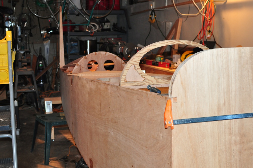
I cutout the turtle deck pieces and sticks, but they are just clamped on at this point. I’m afraid to glue them until I’m sure I won’t need access to the interior area just beneath them.
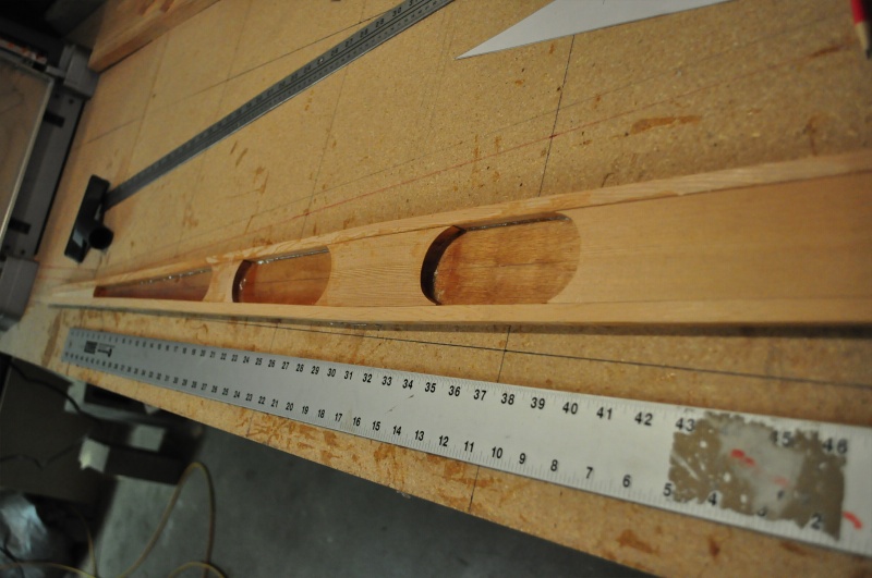
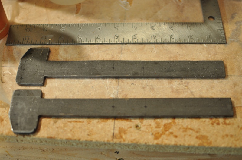
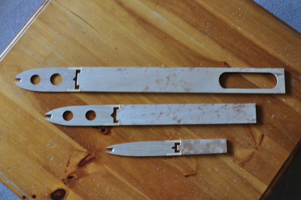
Started cutting my first metal pieces. The two hammer shaped pieces shown below are the wing landing wire anchors. They are nearly 1/5” thick. I was really unsure how I was going to cut them, but it turned out to be relatively easy using a $20 cut-off tool from Harbor Freight. Wish I had a photo of myself cutting them. Sparks were flying everywhere, and the fire alarm kept going off. I think these are the thickest complex metal cuts that you have to make, so I’m confident I can handle all the others. Still need to find a good welder.
March 2011
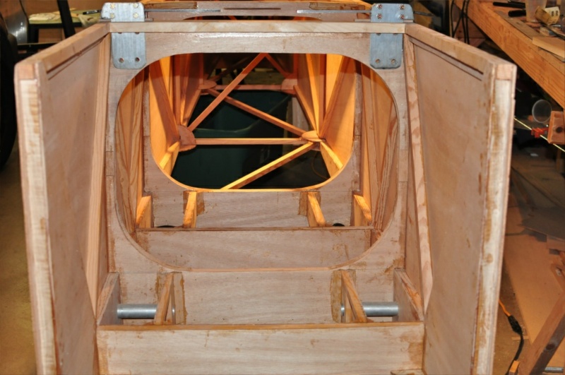
Wing hinge tubes shown below. FlyBaby’s wings can fold for storage or towing.
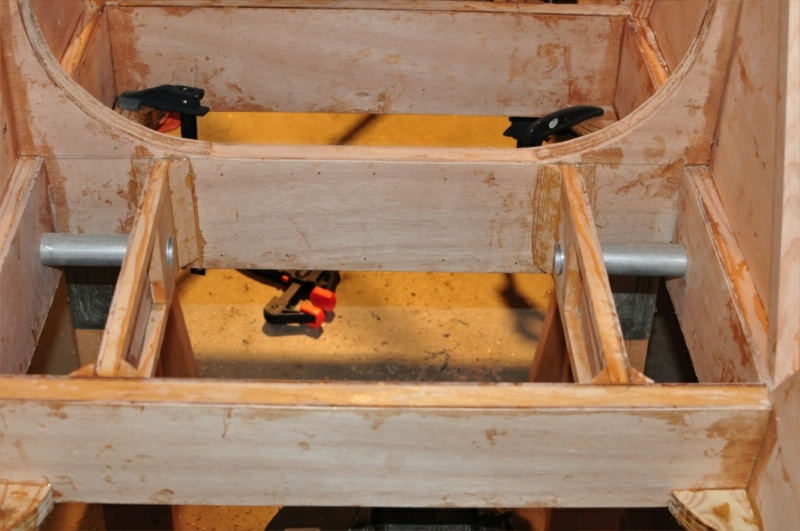
Seat Rails. The fuselage is upside down in this photo.
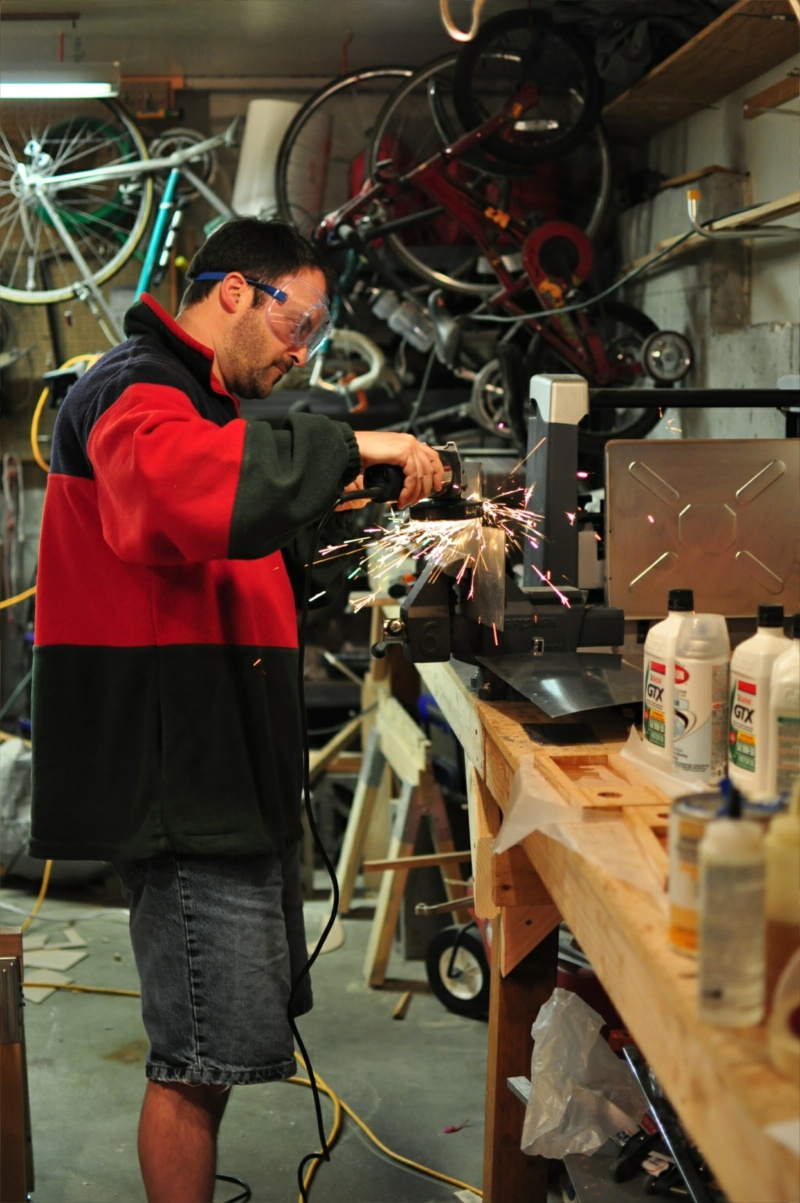
Me cutting metal fittings with a cutoff wheel. (Before I purchased metal cutting bandsaw)
Trial Fit of the Wing Landing Wire anchors. This photo is taken from the front of the fuselage looking toward the rear. Firewall removed.
May 2011
Instrument Panel
Instrument Panel, close up. Front side.
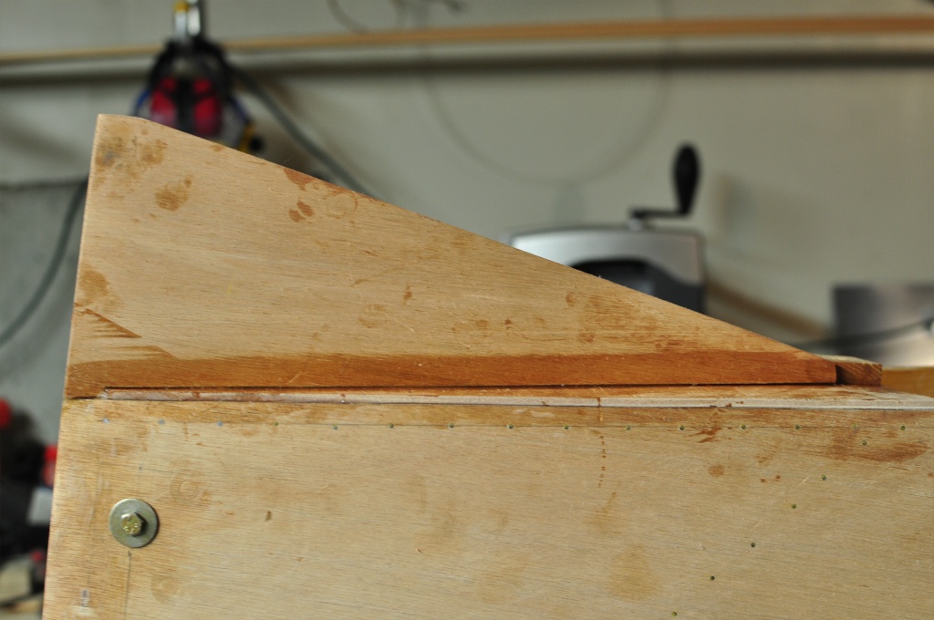
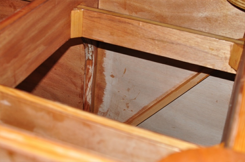
Under fin (Fuselage is upside down)
Under fin (Fuselage is upside down)
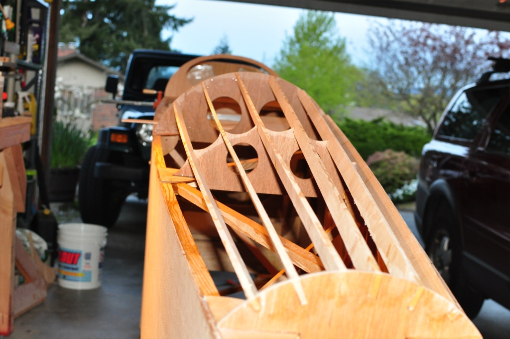
Turtle deck.
Firewall clamped in place, but not glued. I’m holding off as long as possible.
Front trim for Turtle deck.
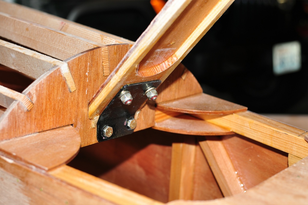
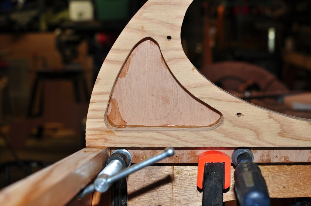
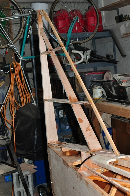
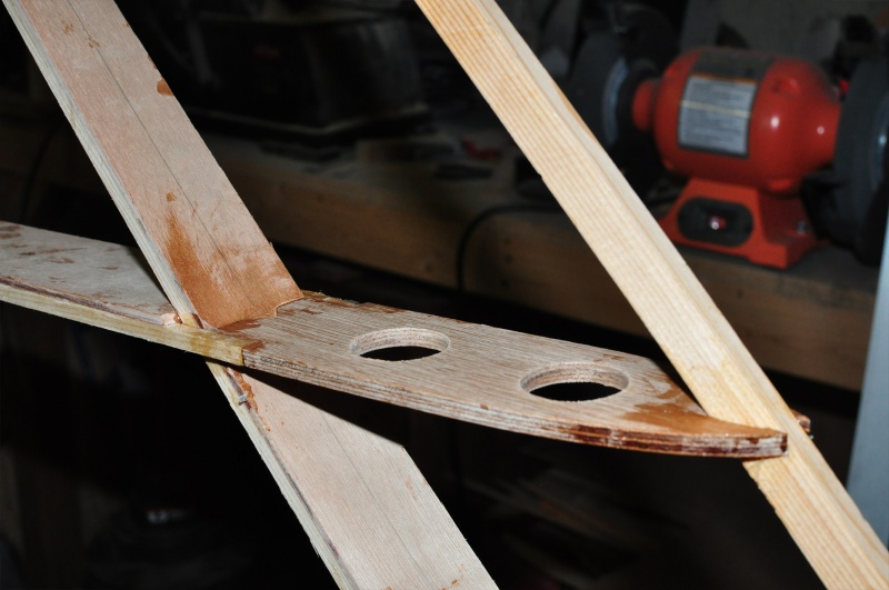
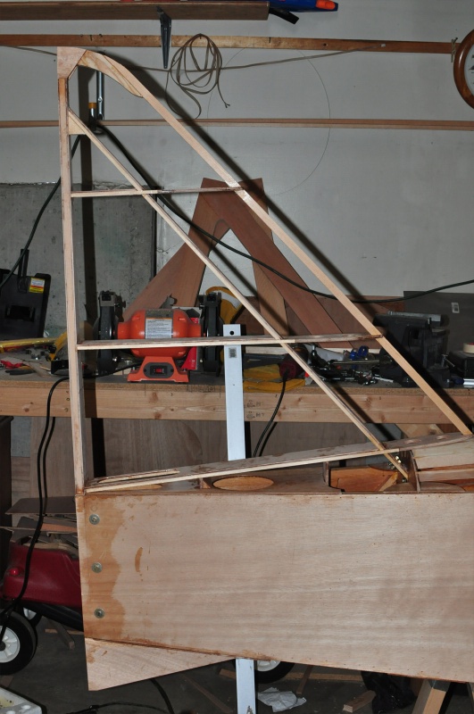
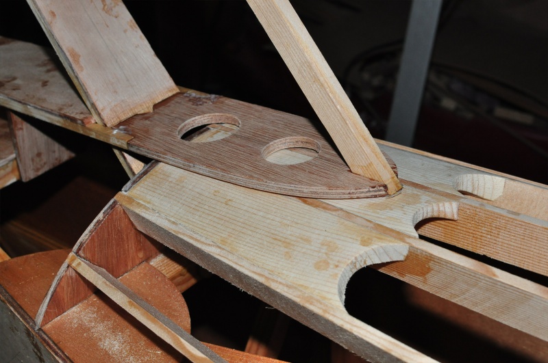
Vertical Stabilizer diagonal spar reinforcement plate.
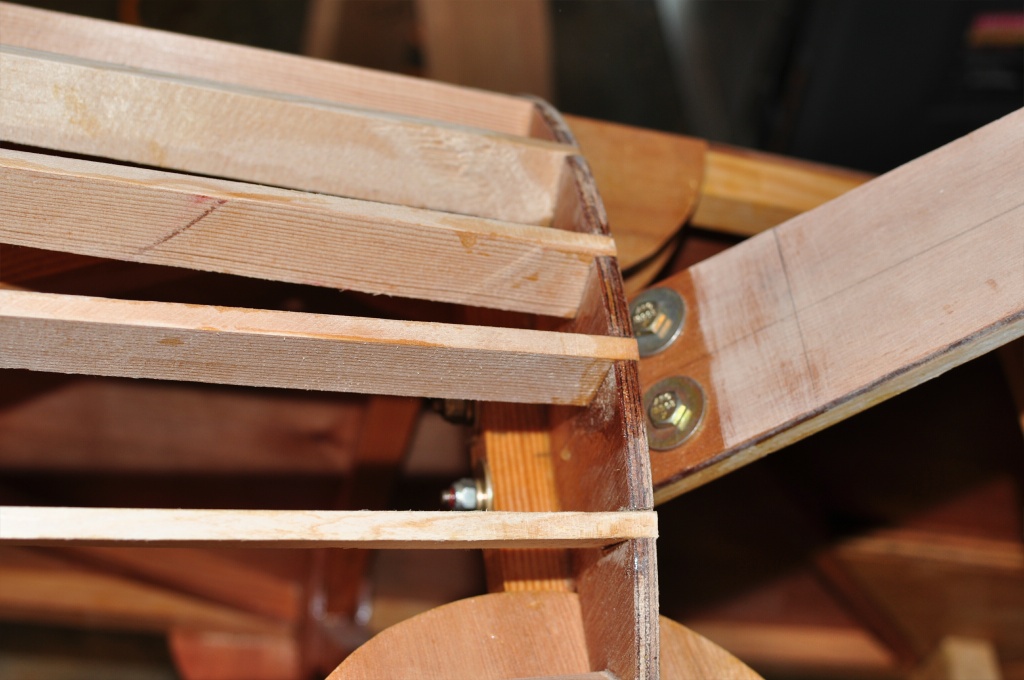
Top view of Vertical Stabilizer where it bolts to fuselage.
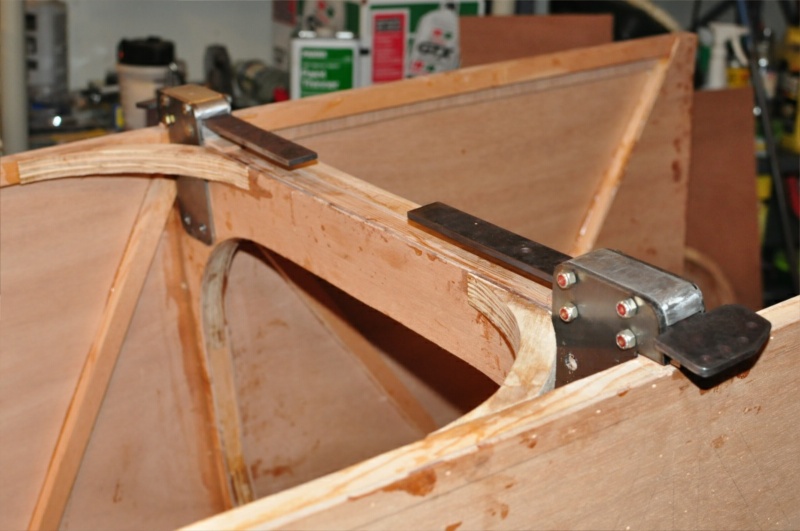
Vertical Stabilizer diagonal spar bolted to fuselage.
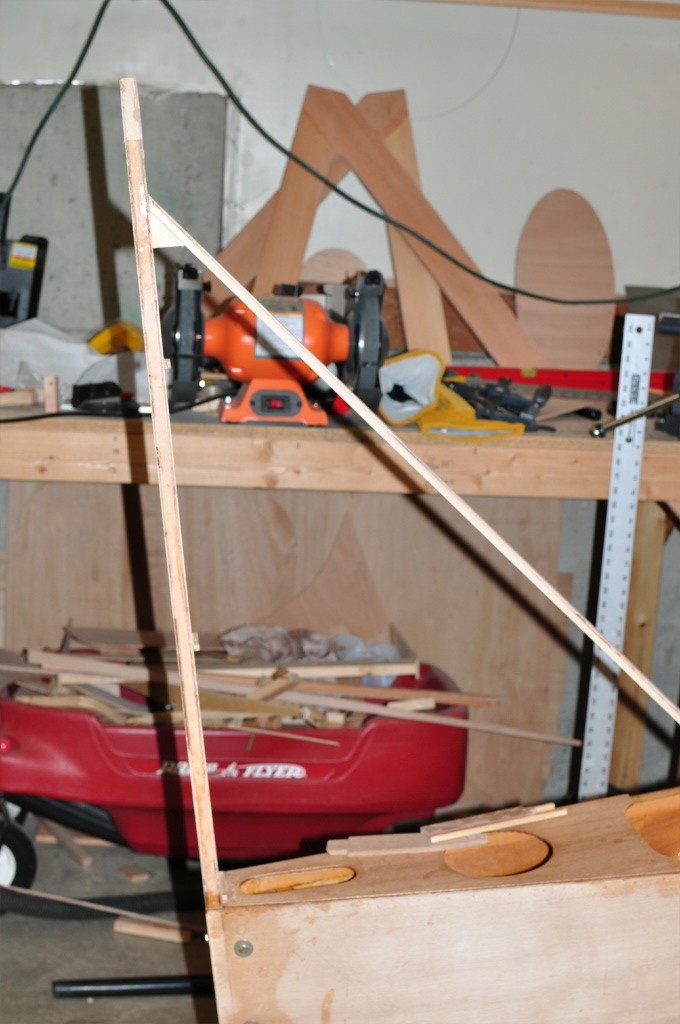
Vertical Stabilizer (Fin) Ribs
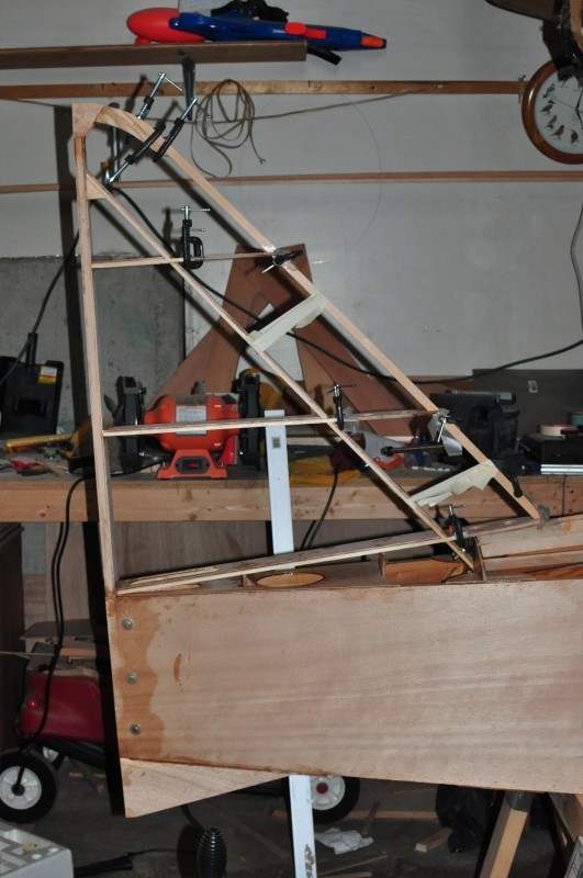
Attaching leading edge and ¼” ribs to vertical stabilizer (fin)
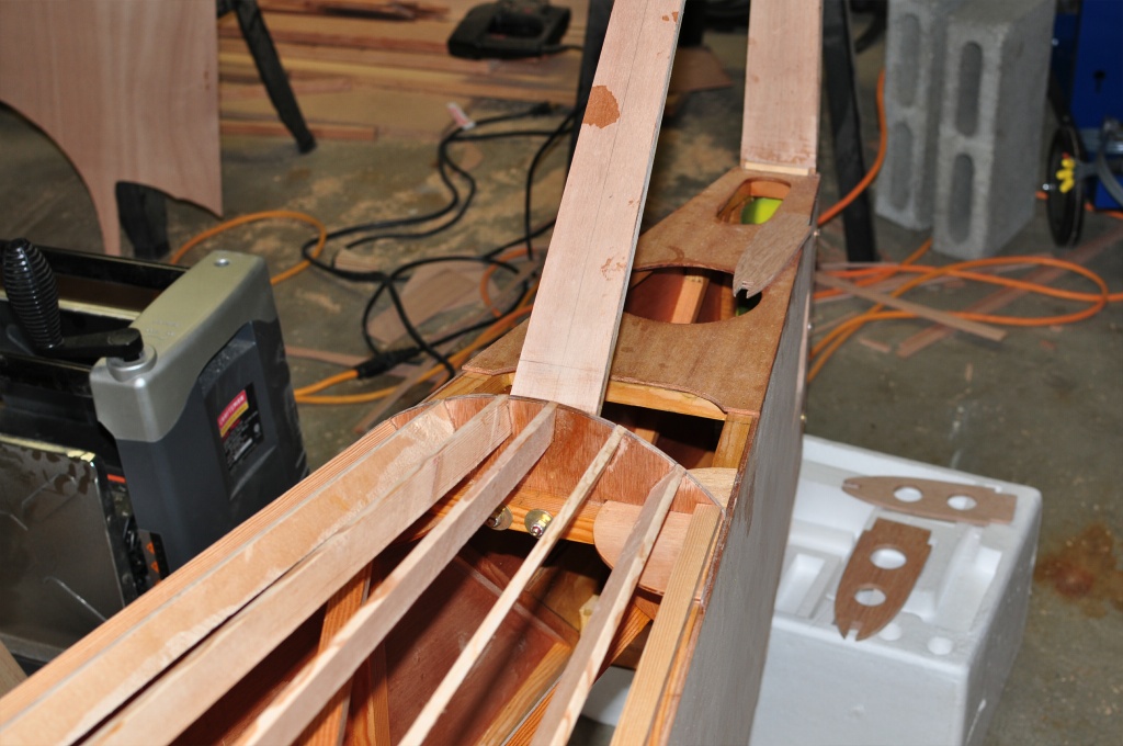
This is the completed vertical stabilizer and under fin. I’m building the tailfeathers mostly out of spruce instead of fir to reduce weight. I’m concerned that sticking with fir might result in CG problems when I’m done.
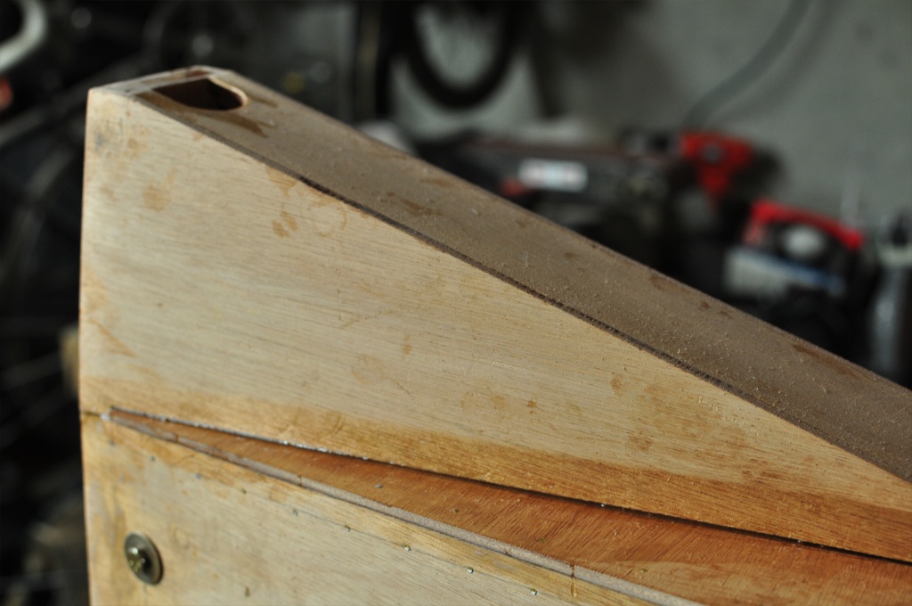
Leading edge of vertical stabilizer where it meets the fuselage. The area between the turtle deck strips is filled in to give the fabric something to attach to.
Panel deviates slightly from the plans.